 One approach to drafting a patent application is to start with the drawings. I think this approach is the probably the best for those embarking on DIY patent drafting.
Once you have the drawings created, writing written description of the patent application, is partially a function of describing what is shown in the drawings and expanding beyond what shown in the drawings. In other words, the drawings can provide the initial road map for drafting the written description. The drawings can be road map because once the parts of the invention shown in the drawings are labeled, you can proceed by describing the parts of the invention and the way that operate or interact with other parts with reference to the parts shown in the drawings.
So, under one approach, to understand how to write a patent application, you must first understand how to create patent drawings. This post provides an introduction to patent drawings.
Table of Contents
- When are Drawings Necessary?
- When are Drawings Not Necessary?
- What Needs to be Shown in the Drawings?
- How Many Drawings Do You Need?
- Drawings for Different Types of Patent Applications
- Black and White Line Drawings
- Types of Drawings Views
- Perspective Views
- Orthogonal Views
- Section Views
- Cut Away Views
- Exploded Views
- Demonstrating Movable Parts and Modes of Operation
- Arrow and Describe
- Broken Lines
- Multiple Drawings
1. When Are Drawings Necessary
Drawings are almost always necessary in a patent application. The relevant statute provides, “The applicant shall furnish a drawing where necessary for the understanding of the subject matter to be patented.” 35 U.S.C. 113. It further states, “When the nature of such subject matter admits of illustration by a drawing and the applicant has not furnished such a drawing, the Commissioner may require its submission…” Id.
This immediately preceding sentence may seem to indicate that you can add drawings after the application is filed if the patent office requires it. However, this is bad strategy. Since you can not add new subject matter to an application after an application is filed, if your written description does not disclose each and every feature of your new drawings, then your drawings submitted after filing may be rejected.
The old saying provides that a picture is worth a thousand words. In patent applications, a drawing is probably worth more than a thousand words. Therefore, a lot of written text description is necessary to describe each and every feature and detail of a drawing. And, you can see that adding drawings after an application is filed carries a high risk of adding new subject matter to the application and therefore begin refused.
Section 113 provides, “Drawings submitted after the filing date of the application may not be used to overcome any insufficiency of the specification due to lack of an enabling disclosure or otherwise inadequate disclosure therein….” In other words, later filed drawings cannot add subject matter to the application.
The bottom line is that you want to submit good drawings with the patent application at the time it is filed.
2. When Are Drawings Not Necessary
Almost never. There are some exceptions, but those exceptions are beyond the scope of this article.
3. What Needs to Be Shown in the Drawings
The first rule is show everything. The next rule is if your not sure whether a feature needs to be shown in the drawings, then show it in the drawings. There is little downside to showing extra details of your invention in the drawings. The more detail the better.
The rules provide that the drawings of an application must show every feature of the claimed invention. 37 C.F.R 1.83(a).
There are times when you can leave details out. But its risky and you should probably ignore all of this information about leaving things out and put everything in. The rule provides, “conventional features disclosed in the description and claims, where their detailed illustration is not essential for a proper understanding of the invention, should be illustrated in the drawing in the form of a graphical drawing symbol or a labeled representation (e.g., a labeled rectangular box).” 37 C.F.R 1.83(a).
For example, look at figure 1 of U.S. Patent No. 5,959,420, (the ‘420 patent) owned by Chrysler.
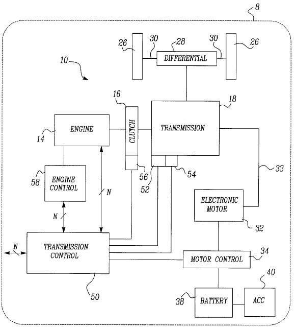
Figure 1 does not show the internal mechanical components of the transmission, engine, clutch, or differential. Those parts are merely abstracted to rectangles. Why? Because the invention is directed to a method of controlling a power train system for a hybrid electric vehicle. Therefore, the focus is on the electronic control and not on the mechanical internal components of the transmission, engine, clutch, or differential.
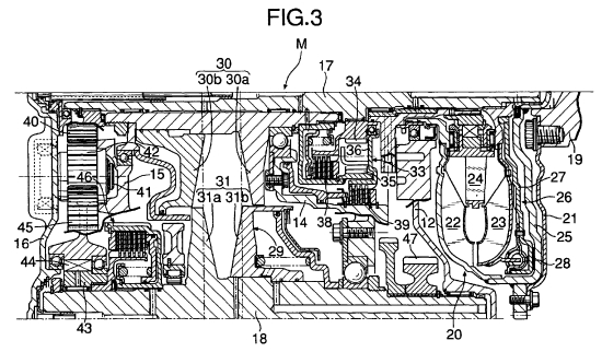
If the ‘420 patent was directed to a new gearing arrangement for a transmission, the transmission could not be shown as a rectangle. Instead the mechanical details of the transmission would need to be shown, probably in multiple drawings. For example, the second view of figure 3 of U.S. Patent No. 6,855,084 shows the internal mechanical components of a portion of a transmission.
Regardless, you must show how the rest of your invention works and interacts with the conventional part. If you leave details of a component out that you should have included, you can irreversibly damage your patent application. Therefore leaving details out of a patent application is risky. So, show all the details of your invention.
4. How Many Drawings Do You Need?
You will need as many drawings as necessary to show the invention, its various parts, and if applicable, all of its stages of operation. At the least, as discussed above, you need as many drawings as are necessary to show every feature of the claimed invention. 37 C.F.R 1.83(a).
Although, it is not a requirement of utility patent drawings, to be safe you could include a perspective view and a view from each side of the invention (top view, bottom, view, front view, back view, right side view, left side view). These view are discussed in more detail below. In some cases, providing all of those views will be more than is necessary, but not detrimental.
In addition, you should include internal views and/or cut away views to show the internal details of the invention in each mode of operating the invention.
5. Drawings for Different Types of Patent Applications
There are at least three broad types of patents. The most common type is a utility patent, which seeks to protect a process or the way the invention functions or operates. The next type of is a design patent, which seeks to protect the appearance of the invention. The last type is a plant patent, which is rare and will not be discussed here. In this article, I will discuss utility patent drawing. In a future post, I will discuss design patent drawings.
6. Black and White Line Drawings
Normally black and white line drawings are required. 37 CFR 1.84(a)(1). There are some exceptions to this rule that allow for submitting color drawings, grayscale drawings, or photographs. But, the USPTO has particular rules that you must comply with before you can submit color drawings or photographs. See 37 CFR 1.84(a)(2), (b). Here, I’ll focus on line black and white drawings. And you probably should too.
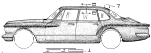
Below is an example from U.S. Patent App. Publication No. 2014/0109700. Figure 11 shows the a gray scale drawing and figure 12 shows a black and white line drawing of the same part with items 44 and 18 in a vertical position. Generally, you should avoid gray scale or color drawings and instead provide black and white line drawings for patent applications, such as shown in figure 12.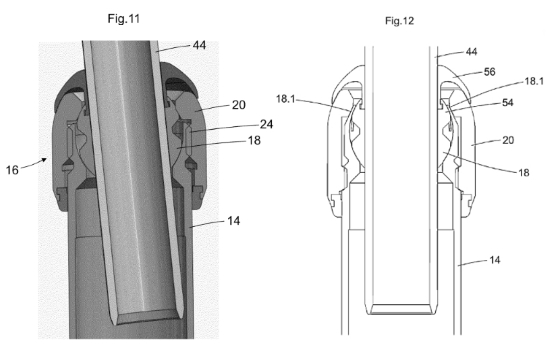
Figure 12 is a section view and ideally the section cut surfaces would be shown with a cross-hatching pattern as discussed below. Nonetheless, figures 11 and 12 demonstrate the difference between gray scale drawings (figure 11) and black and white line drawings (figure 12) generally.
7. Types of Drawing Views
There are a number of different types of views of the invention that can be shown in the drawings. I will discuss here perspective, orthogonal, section, cut away, and exploded views. I will also cover how to demonstrate movable parts in an invention. I will cover flow charts, block diagrams, and graphs in a future post.
A. Perspective Views
There’s no rule about what the first drawing should be. However, generally I like to start with a perspective view of the overall invention if it is available. Starting with a perspective view of the invention as figure 1 quickly provides the reader of your patent application with a quick general understanding of your invention.
A perspective view provides a three dimensional representation of the invention from an angle to showing depth. In contrast an orthogonal view, with provides a two-dimensional representation of a side of the invention.
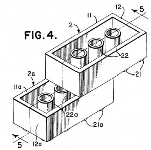
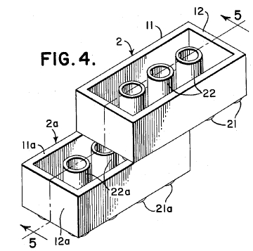
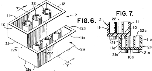
What does a perspective view look like? Look at Figure 4. It is from US Patent 3,005,282 (the ‘282 patent) on the Lego toy building block. Figure 4 shows a bottom front perspective view of two building blocks joined together. It also shows one mode of operation of the invention, i.e. one way of connecting two blocks.
Figure 4 provides vertical line shading. Line shading is nice, but not entirely necessary in utility patent drawings, unless showing the curvature or surface treatment of a surface or component is important to the invention. Even when it is important, it might be possible to describe those features in words in the written description rather than show them with line shading.
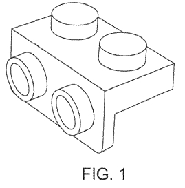 While figure 4 shows the block from a bottom front perspective view, figure 1 from US Patent D688328 (the ‘328 patent) shows a different type of block from a more traditional front (top) perspective view. Also, note that figure 1 does not have any line shading.
Perspective views enable the viewer to more quickly understand the invention, because view more closely replicates what a person would see of the object in real life, as compared to orthogonal views discussed next.
B. Orthogonal Views
An orthogonal view show the invention where one side of the invention is parallel to the drawing surface. Common orthogonal views are a front view, back view, top view, bottom view, right side view, left side view. Below are orthogonal views from the ‘328 patent.
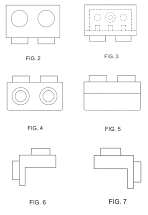
As described in the ‘328 patent FIG. 2 is a top view, FIG. 3 is a bottom view, FIG. 4 is a front view; FIG. 5 is a rear view, FIG. 6 is a right side view, and, FIG. 7 is a left side view.
As you can see it is much easier to quickly understand the invention from a perspective view than it is from studying orthogonal views.
How do you determine what is the front view? Sometimes it is not inherently clear which side is the front side of an invention. In such case, you–the drafter–get to decide. All the remaining common orthogonal views follow from the decision of what is the front view, e.g. the rear side is opposite the front side, the top side is opposite the bottom side, and the right side is opposite left side.
In a utility patent application, it is not always necessary to include all of the common orthogonal views. For example, the the ‘283 patent on the Lego block provides only one orthogonal view in figure 2, which is a bottom view (not counting figures 8 through 12 which are of a different variation of the block as compared to that of figure 1). The remaining drawings of figure 1-8 are either a perspective view (figures 1, 4, and 6) or a section view (figure 3, and 5).
C. Section Views
Sometimes it is necessary to show the internal parts and components of a device. To do that, a section view is often used. The section view is taken along a plane that intersects the device/object. Figure 5 of the ‘282 patent provides a section view of the interlocked blocks from figure 4.
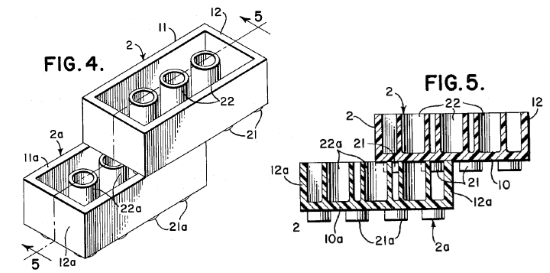
Look back to figure 4 and notice that figure 4 has the number “5” located in two places next to arrows on opposite sides of the blocks. Those arrows intersect a broken line that runs along the length of the block and demonstrates the plane along which the section is cut. The arrows show the direction the section view. And the use of the numeral “5” generally indicates the figure in which the section view is provided, e.g. figure 5.
In figure 5, the surface that is “cut” by the section plane is provided with diagonal hatching lines to indicate the section surface. Sometimes the hatching lines are different widths, such as the thin and thick hatching lines of figure 5. And sometimes the hatching lines are all the same width. The section hatching should provide “regularly spaced oblique parallel lines spaced sufficiently apart to enable the lines to be distinguished without difficulty.”
In the case of figure 5, the section view allows you to see the interaction and connection of the projections 21 of one block with interior and the secondary interior projections 22 of the other block when the blocks are connected as shown in figure 4.
As another example, figure 7 of the ‘282 patent provides a section view along the line 7–7 from figure 6.
D. Cut Away Views
Another way to demonstrate the interior components of an object is to cut away portions parts in the drawing. In a cut away view, only portion(s) of the object are cut as distinguished from a section view where all of the object is cut along the section plane.
Figure 2 from U.S. Patent No. 2,929,922 shows a cut away view of a laser. The cylindrical walls of items 19, 22, and 27 are cut and the location of the cut has section hatching to indicate a cutaway. The cutaway allows a view of items 16, 16a, 17, an 18. 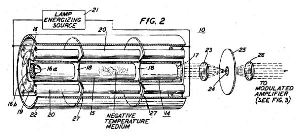
E. Exploded Views
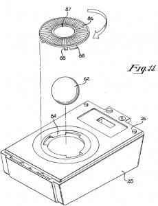
An exploded view allows you to show the relationship and order of parts in an assembly. Figure 11 of U.S. Patent No. 4,464,652 shows an exploded view of a computer mouse. This type of mouse has a ball for tracking the movement of the mouse. The ball 62 and the cap lock 86 are each shown with broken projection lines showing where each would be located in the finally assembled mouse. In addition the curved arrow adjacent the cap lock 86 shows the direction of rotation when the cap lock meets the ridges 84 of the main body 26.
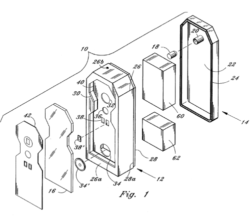
If projection lines showing the path of the parts are not used, a bracket should be used to show all the parts the are a part of the exploded assembly. For example, Figure 1 of U.S. Patent 5,526,536 provides a bracket at 10 demonstrating that parts 42, 16, 12, 60, 62, and 14 are all a part of the exploded assembly. While some projections lines (e.g. between parts 18 and 20) are used in Figure 1, projection lines do not connect all of the parts, so a bracket is necessary.
8. Demonstrating Movable Parts and Modes of Operation
There are a number of ways of demonstrating the movement or multiple positions of a part(s) in an invention.
A. Arrow and Describe
The first way is to provide an arrow on the drawing and describe in the text how the object moves and interacts with the other parts of the invention. This was done in figure 11 of the Apple mouse patent shown above. A curved arrow is shown adjacent to the locking cap 86. The text description explains that “In operation, a user desiring to insert or remove ball 62 from the cursor control unit 20, may unlock and remove the lock cap 86 from the orifice 82 by simply rotating the cap such that the tabs 88 and ridges 84 no longer interleaf.”
B. Broken Lines
The Wright Bothers Patent No. 821,393 on a flying machine shows the use of broken lines to demonstrate a moved position of the wings in figure 1. The broken lines at items c and g and items a and e show those portions of the wing in a raised position. The broken lines at items b and items f and d show those portions of the wing in a lowered position. The solid lines show the home position of the wing.
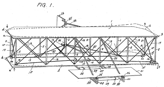
Regarding alternative or moved positions of parts, the USPTO says, “A moved position may be shown by a broken line superimposed upon a suitable view if this can be done without crowding; otherwise, a separate view must be used for this purpose.” So, next we will discuss the use of multiple views.
C. Multiple Drawings
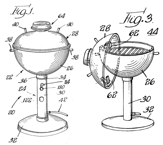
The third way to demonstrate the movement or multiple positions of parts is to create a drawing showing the part in each of its positions. The charcoal grill of US Patent No. 3,688,758 shows the grill with the lid 28 closed on top of the grill in figure 1 and the lid hanging by hanger 62 off the side of the grill in figure 3.
This post provides a introductions to patent drawings. In future posts, I’ll cover other aspects of patent drawings and other types of drawings, such as flow charts, block diagrams, and graphs.